Waste Form
The Waste Form Process Model represents waste package degradation and waste form dissolution for the simulation of a nuclear waste repository. It has been developed under the Generic Disposal Systems Analysis (GDSA) work package, which is under the Spent Fuel and Waste Disposition Program of the U.S. Department of Energy (DOE) Office of Nuclear Energy, as part of the Spent Fuel and Waste Science and Technology (SFWST) Campaign. Development of the Waste Form Process Model is ongoing, and lead by Jennifer Frederick, Paul Mariner, and Glenn Hammond.
The GDSA work package is responsible for developing disposal system modeling and analysis capability that: (i) spans a wide range of disposal options, and (ii) must accurately consider unique waste package designs specific to each disposal system. Therefore, the ability to represent the large amount of possible waste package designs within the process model is essential. This is accomplished through modularity. The Waste Form Process Model in PFLOTRAN consists of three main components: (a) the waste form canister, (b) the waste form object, and (c) the waste form release mechanism.
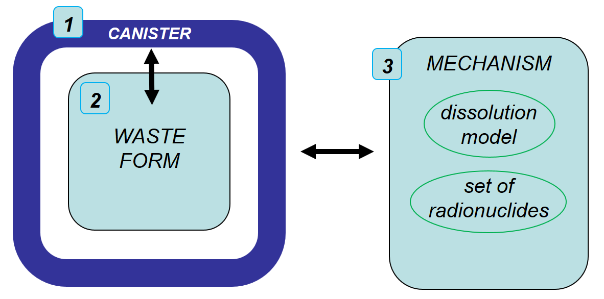
The three main components of PFLOTRAN’s Waste Form Process Model consists of the waste form canister, the waste form object, and the waste form mechanism.
Waste Form Canister
The waste form canister conceptual model addresses (1) the timing of canister
breach and (2) the performance of the canister after breach. This model can be
turned on by including the CANISTER_DEGRADATION_MODEL sub-block within the
MECHANISM block. In this conceptual
model, the status of the canister is defined by two abstract terms, canister
vitality and canister performance. Canister vitality is a normalized measure of
remaining time or remaining canister wall thickness before canister breach,
and canister performance is a normalized measure of the physical ability of the
canister to contain the source. Initially, both terms have a value of 1. Before
canister breach, while corrosion reduces the time remaining or canister wall
thickness remaining before canister breach, the canister vitality decreases.
When it reaches zero, the canister is breached and canister performance begins
to decrease.
To date, canister performance has not yet been implemented in the waste form canister component, but a framework for canister vitality is complete. In this framework, canister vitality is initialized to 1, and is reduced at each time step by the effective canister vitality degradation rate \(R_{eff}\), according to
where \(R\) is the base canister degradation rate at 60C, \(T\) is the
local temperature (in Kelvin), and \(C\) is the canister material constant.
This equation assumes that reaction rates are a function of temperature as
described by the Arrhenius equation. For general corrosion, \(R\) would
represent the general corrosion rate at 60C in units of L/T, and the associated
canister vitality would be a measure of the remaining normalized canister
thickness before breach. The value for \(R\) can be specified using the
CANISTER_VITALITY_RATE keyword under the WASTE_FORM sub-block.
Alternatively, parameters that define a normal distribution for the value of
\(log_{10}\left({R}\right)\) are given in the CANISTER_DEGRADATION_MODEL
sub-block using the keywords VITALITY_LOG10_MEAN, VITALITY_LOG10_STDEV,
VITALITY_UPPER_TRUNCATION, for mean, standard deviation, and the upper
truncation, respectively. The value for \(C\) is specified using the
CANISTER_MATERIAL_CONSTANT keyword. Finally, Equation
(1) can be ignored by the Waste Form Canister
component, and a specific canister breach time can be specified instead of
assigning \(log_{10}\left({R}\right)\) or \(R\) by including the keyword
CANISTER_BREACH_TIME under the WASTE_FORM sub-block. Once canister
vitality drops below zero, the canister is considered breached, and a Boolean
flag is turned on for the waste form object inside of it, allowing the waste
form inside to begin dissolving.
Waste Form Object
The second component of the Waste Form Process Model is the waste form object.
This object is generic and contains only the information that is required by all
waste form types. The user defines each waste form object’s location in the
domain via the REGION keyword or the COORDINATE keyword, as well as its
initial volume via the
VOLUME keyword, and exposure factor (a surface area multiplying factor to
the waste form’s effective dissolution rate) via the EXPOSURE_FACTOR
keyword. Within the waste form object, the value of its effective dissolution
rate is stored. Each waste form object has a pointer to the waste form mechanism
(the third component of the process model), specified by the MECHANISM_NAME
keyword, that describes waste form type-specific information. The dissolution
equation that defines the effective dissolution rate is obtained from the waste
form mechanism. The waste form object also stores the concentrations of the
radionuclide inventory. The initial radionuclide inventory is obtained from the
waste form mechanism.
Radionuclide decay and ingrowth is, by default, internally calculated for the
set of radionuclides in each waste form according to a 3-generation analytical
solution derived for multiple parents and grandparents and non-zero initial
daughter concentrations (see Section 3.2.3 of Mariner et al. (2016),
SAND2016-9610R). The solution for radionuclide concentration within the waste
form is obtained explicitly in time. Internal calculation of radionuclide decay
and ingrowth also allows the calculation of instantaneous release
fractions for certain radionuclides upon canister breach. A fully-implicit
solution for multiple-parent, single-daughter radioactive decay and ingrowth
can be optionally applied by including the keyword IMPLICIT_SOLUTION within
the WASTE_FORM_GENERAL block. The implitcit solution is documented
below.
Upon canister breach, the waste form object begins to dissolve according to the dissolution model that is defined by the waste form mechanism to which the waste form object points. Waste form volume decreases accordingly. The effective dissolution rate along with the radionuclide concentrations in the waste form, determines the source term (radionuclide release rate) for each waste form.
Waste Form Mechanisms
The third component of the Waste Form Process Model is the waste form mechanism.
In contrast to the other two components, this object is specific to the type of
waste form being simulated and contains information which defines the behavior
of each specific waste form type. The mechanism contains the value of the waste
form bulk density specified via the MATRIX_DENSITY keyword, the set of
initial radionuclides via the SPECIES sub-block (initial mass fractions,
molecular weights, decay rates, daughter species, and instantaneous release
fractions), and a pointer to the waste form dissolution model. In some cases,
it also stores the waste form specific surface area via the
SPECIFIC_SURFACE_AREA keyword. The following types of waste form mechanisms
are available to the user:
GLASS Mechanism
High level waste in the form of glass logs are simulated using the GLASS mechanism. The glass dissolution model used in this mechanism is given by
where \(K_0\) is the intrinsic glass dissolution rate in units of kg
m-2day-1, \(\eta\) is a unitless pH dependence term,
\(pH\) is the value of the pH (unitless), \(E_a\) is an effective
activation energy in units of J mol-1, \(R\) is the universal
gas constant in units of J mol-1K-1, \(T\) is the
temperature in Kelvin, \(Q\) is an ion activity product of the glass
dissolution (activity of H4SiO4), \(K\) is the equilibrium
constant for the rate limiting step (activity of H4SiO4 at
saturation with the glass), \(V\) is an exponent term to the affinity term,
and \(K_{long}\) is the long term dissolution rate when the pore fluid
solution is at saturation with SiO2 in units of kg m-2day-1. Two of these parameters (pH and Q) can be calculated as part of
the simulation using the built-in geochemistry capability in PFLOTRAN rather
than specifying a constant value. Rather than specifying a value for PH
and Q keywords, one would specify AS_CALCULATED.
This equation can be simplified to the rate specified by Kienzler et al. (2012) as
by specifying KIENZLER_DISSOLUTION. The units of \(R_g\) are kg
m-2day-1. The dissolution rate for glass is multiplied by
a specific surface area, in units of m2 kg-1, via the
SPECIFIC_SURFACE_AREA keyword, giving a
fractional dissolution rate in units of T-1.
DSNF Mechanism (instantaneous)
For the Instantaneous mechanism (currently called DSNF mechanism in PFLOTRAN),
at the time step when canister breach occurs the fraction of the radionuclide
entered by the user in the SPECIES sub-block under instantaneous release fraction,
is released over the length of the time step and in the next time step the
rest of the radionuclides are released. This is accomplished by internally
setting the fractional dissolution rate to the value of 1/dt, where dt
is the length of the current time step at breach. Concurrently, the volume of
the waste form is reduced to zero. The user must enter 1.0 for all instaneous
release fractions, for all the radionuclides to be released in the time step
that the canister vitality reaches zero. Metallic defense-related spent nuclear
fuel (DSNF) is simulated using this mechanism.
FMDM Mechanism
Used nuclear fuel (composed of uranium dioxide) is simulated using the Fuel Matrix Degradation Model (FMDM) mechanism. This mechanism also demonstrates how external dissolution models can be coupled to PFLOTRAN. The dissolution model used is obtained via coupling to the FMDM by calling a single external subroutine developed by Jerden et al. (2015). Details regarding the FMDM conceptual model and algorithmic design are provided by Jerden et al. (2015). This mechanism requires the free ion concentrations of O2(aq), HCO3-, H2(aq), and Fe++ to be specified in mol/L in the CONCENTRATIONS sub-block card of the CONSTRAINT card.
FMDM Surrogate Mechanism
Surrogate model developed for the FMDM mechanism. It is a feed-forward neural network with two hidden layers or a k-Nearest Neighbors regressor (kNNr) implemented in PFLOTRAN. Age of the fuel prior to the beginning of the simulation is specified through the DECAY_TIME sub-block card of MECHANISM FMDM_SURROGATE or FMDM_SURROGATE_KNNR for kNNr. The epsilon value for considering a zero distance to the nearest neighbor can be specified through the KNNR_EPS sub-block card. The coefficients for the neural network model and the FMD generated table for the kNNr are contained in HDF5 databases and can be found in PFLOTRAN_SRC/regression_tests/ufd/. They are read in by PFLOTRAN and therefore must be in the directory it is executed in. The number of nearest neighbors for the kNNr must be specified in the HDF5 database. This mechanism requires the free ion concentrations of O2(aq), HCO3-, H2(aq), and Fe++ to be specified in mol/L in the CONCENTRATIONS sub-block card of the CONSTRAINT card.
WIPP Mechanism
The Waste Isolation Pilot Plant (WIPP) mechanism simulates a waste panel in a mined salt repository. It is essentially identical to the DSNF (instantaneous) mechanism.
CUSTOM Mechanism
To allow additional flexibility, the CUSTOM mechanism was created so that a user can specify a fractional dissolution rate (in units of 1/T), or a waste form dissolution rate that is based on specific surface area (in units of M L-2 T-1). If the user specifies a surface area dependent dissolution rate, a specific surface area (in units of L2 M-1) must also be provided.
Implicit Solution for Radionuclide Decay and Ingrowth
The user can specify the keyword IMPLICIT_SOLUTION within the
WASTE_FORM_GENERAL block to solve for decay and ingrowth using an implicit,
direct solve of the Bateman equations for any number of generations. The
governing equation for isotope decay and ingrowth is,
which describes the change in isotope concentration over time (\(\frac {d C_i(t)} {d t}\)) due to its own decay (if any) (\(-\lambda_i C_i(t)\)) plus ingrowth (if any) from the isotope’s parents (\(\lambda_p S C_p(t)\)), where \(\lambda\) is the decay rate constant [1/sec] and \(S\) is a stoichiometry coefficient. The equation is discretized and rewritten in terms of a residual equation as follows,
where \(f\left({c^{k+1,p}}\right)\) is the residual, \(c^{k+1,p}\) is the solution for concentration at the \(k+1\) time step and the \(p^{th}\) iterate, \(\frac {c^{k+1,p} - c^{k}} {\Delta t}\) is the discretized accumulation term (e.g., the left hand side of the governing equation above), and \(R\left({c^{k+1,p}}\right)\) is the source or sink term (e.g., the right hand side of the governing equation above).
A Jacobian matrix is formed according to,
which is a matrix of all the partial derivatives of the solution with respect to each unknown variable. Using Newton’s method, which solves the following system,
the concentration can be updated according to,
Note: The governing equation is reformuated in terms of isotopes and the isotopes’ daughter(s) in the source code, rather than the isotopes and isotopes’ parent(s) formulation shown here.
References Cited
Jerden, J., G.E. Hammond, J.M. Copple, T. Cruse and W. Ebert (2015), Fuel Matrix Degradation Model: Integration with Performance Assessment and Canister Corrosion Model Development. O. o. U. N. F. Disposition. FCRD-UFD-2015- 000550. US Department of Energy, Washington, DC.
Kienzler, B., M. Altmaier, C. Bube and V. Metz (2012). Radionuclide Source Term for HLW Glass, Spent Nuclear Fuel, and Compacted Hulls and End Pieces (CSD-C Waste). KIT Scientific Reports 7624. Karlsruhe Institute of Technology, Baden- Württemberg, Germany.
Mariner, P.E., E.R. Stein, J.M. Frederick, S.D. Sevougian, G.E. Hammond, and D.G. Fascitelli (2016), Advances in Geologic Disposal System Modeling and Application to Crystalline Rock, FCRD-UFD-2016- 000440, SAND2016-9610R, Sandia National Laboratories, Albuquerque, NM.
P.E. Mariner, L.A. Connolly, L.J. Cunningham, B.J. Debusschere, D.C. Dobson, J.M. Frederick, G.E. Hammond, S.H. Jordan, T.C. LaForce, M.A. Nole, H.D. Park, F.V. Perry, R.D. Rogers, D.T. Seidl, S.D. Sevougian, E.R. Stein, P.N. Swift, L.P. Swiler, J. Vo, and M.G. Wallace (2019). Progress in Deep Geologic Disposal Safety Assessment in the U.S. since 2010, M2SF-19SNO10304041, SAND2019-12001R, Sandia National Laboratories, Albuquerque, NM.